This is a short one, but a good one!
See the video for full assembly instructions, as well as my first powered test, and find the files for download here if you’d like to try it out.
This is a short one, but a good one!
See the video for full assembly instructions, as well as my first powered test, and find the files for download here if you’d like to try it out.

In the last post we got a working differential together, since then I have been designing the axle tubes, axle shafts and the drive shaft.
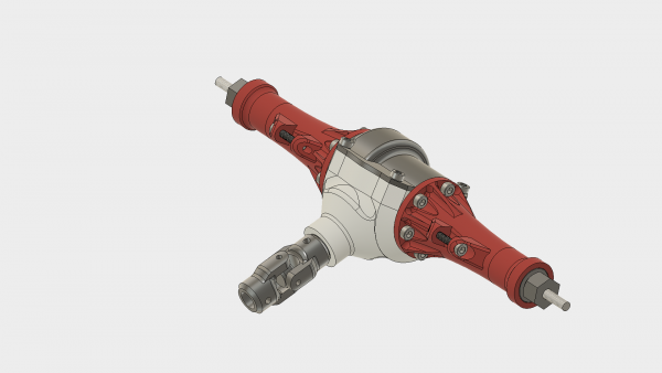
I have mentioned from the beginning that I am trying to keep the complex mechanical components compatible in size with off-the-shelf RC components, so I have made the width of the axle and the mounting points exactly the same as the Boom Racing SCX10 axle that I used on my rat rod build.

Printable rear axle with differential compared to Boom Racing SCX10 axle for size
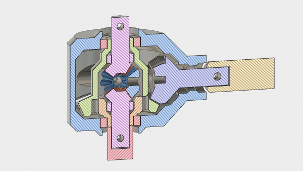
The housing of the differential has been redesigned so that all of the tolerances are contained within one part, and the cover simply screws down on top, holding the two largest bearings in place. Nothing has an overhang more than 45 degrees, so it is all printable without support.

Inside the axle tubes there are two bearings which support the printable axles shafts. The axles shafts have provision for an M4 rod down the middle, which provides both strength and the opportunity to use standard RC wheels if desired.


I printed and assembled prototypes based on this design and it went together well. My plans to test immediately were delayed due to some mistakes I made in the sizing of my driveshaft, but the assembly feels satisfactory when turned by hand, I have high hopes for the first test!

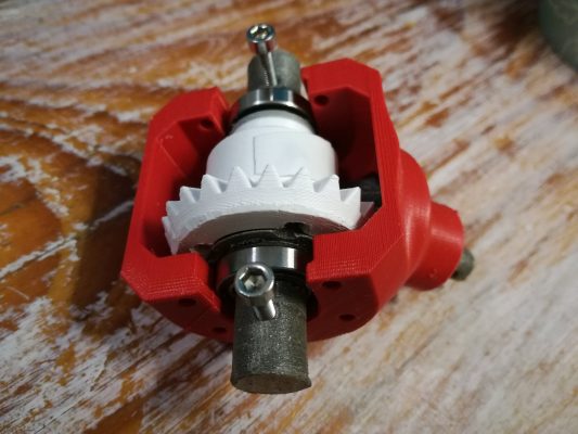
The assembly, printed in ABS filament
Stay tuned for the assembly and test video of the rest of the axle shortly, as well as work on the drive shaft and universal joints.

Robox AutoMaker software update is now live. Start your AutoMaker installation to find the update automatically or download it from here www.cel-robox.com/downloads/.
Your firmware will need to be updated as requested by the software, please note that the Robox will restart when the firmware update completes so be sure it has finished printing before allowing the update.
When you connect a Root or Mote device it will require an update to be able to communicate with AutoMaker, this will be shown as a button in the Network menu in AutoMaker preferences page.
Major changes:
A big welcome to our new software developers Tony and George, this is the first AutoMaker update they have worked and is just a small step on the path toward a lot of new content.
If you have problems a clean install might help.
https://robox.freshdesk.com/support/solutions/articles/1000155625-clean-install
Please create new posts for any problems you have.

Over the past few weeks, with a brief hiatus due to international travel for my day job (I’m an Electrical Engineer in the telecoms industry), I have been plugging away at the design of the rear differential.
I have a few design goals for the rear axle
Of course the rear axle can be made significantly smaller (or stronger, in the same envelope) if we go from a open differential to a spool, which will be a suitable modification if it is to be used on a rock crawler.
I first attempted to design from the outside inwards, starting with my goal diameter for the differential and designing gears to fit inside it. This turned out to be a bad idea, causing endless redesign, it was much more sensible to design the gears and build the casing around it.
There are other aspects to keep in mind, almost all of them relating to tolerances. For example, if a bearing recess is part of the face that contacts the printer bed then the slight bulging can prevent the bearings from fitting.
Unfortunately Fusion360 doesn’t have a decent tool to create parametric bevel gears and designing them properly yourself is no mean feat. This is a real nuisance because we have to import gears from elsewhere and then design around them.
Fortunately there is a very nice script written for OnShape which you can find here and it is not too much trouble to set them up as you like, export as STEP files and import into Fusion360.
In order to keep my design “semi parametric” I positioned all of the gears sensibly with respect to the origin, and then defined variables which correspond to the gears dimensions. So long as all of the dimensions of the housing correspond to these variables and aren’t referenced to the gear objects themselves it is fairly easy to swap the gears out with others.
This iteration of the design provides another approximately 2:1 reduction, which means that we should be able to shrink the transmission that was designed in the last post.


This is more of a personal lesson, but perhaps it is worth reminding. If you are like me then you design something to 85% and then realize that you could have designed it better, then you repeat the process, without ever printing anything. With something that takes 100’s of hours to print that may make sense, but for tiny parts like this it is just foolishness. There is a lot to be learned by just printing the item, and trying it out as is.
These are pictures of the first functional assemblies, hastily printed in ABS (not printed on a Robox, I look forward to seeing how well it handles the small pieces though!).


Some things are best expressed in video, and assembly is one of those things, so here we go!
![]()
King Edward VI Community College


